ILLUSTRATED SCHEMATICS
For Adafruit's original schematic, click here.
The original schematic can be a bit intimidating and confusing. So here are some illustrated schematics.
I am aware that it looks like a kindergartner drew them.
These were edited using Gimp, a powerful open source image editing program. Go open source!
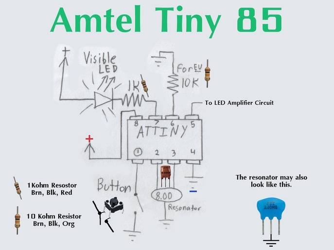
Above is the 'main part'. The Amtel Tiny 85 is the micro-controller used for this project. The micro-controller must be programmed with the TV-B-Gone firmware available here. Pin 1 on the actual chip is indicated by a circle, just like in the picture.
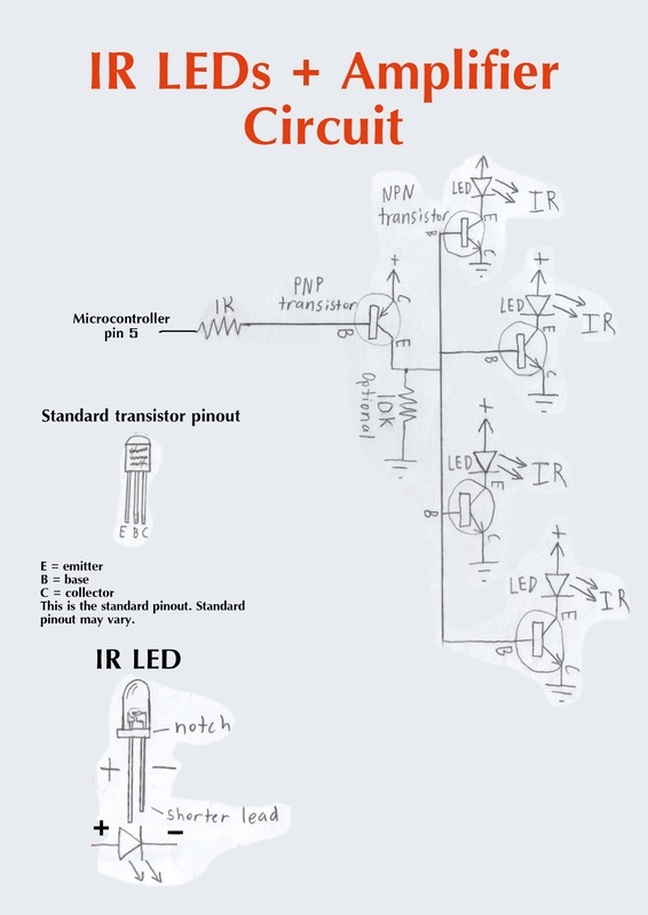
This picture is of the IR LEDs and the transistors. The signal coming from the micro-controller is not powerful enough to power the 4 high power IR LEDs, so the signal from the micro-controller is amplified by a few transistors. The picture of the transistor pin-out is only the most common pin-out. Keep in mind that THE PIN-OUT OF YOUR TRANSISTORS MAY VARY! be sure to check the data-sheet for your specific transistor. The IR LEDs are polar. If you hook them up backwards even for a few seconds, they will permanently break. Take note of the IR LED picture above, and learn to recognize the + and - sides.
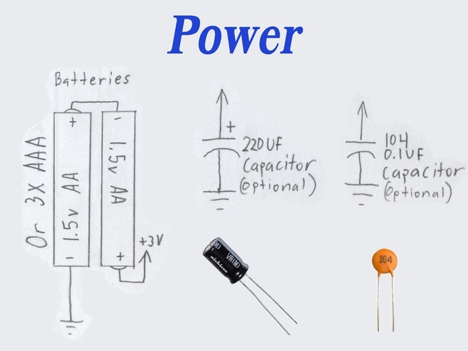
Above is the power circuit. The standard kit is powered by 2x AA batteries. One alkaline cell is about 1.5V, and we are using 2x AA cells, totaling 3V. The ATtiny can handle up to about 5V, so you can also power the TV-B-Gone with a Lithium cell. Lithium-ion polymer battery cell is 3.7V. A Lithium cell would give your TV-B-Gone a little bit more range. You can also connect 3x AAA batteries totaling 4.5V for more range.
The 2 capacitors (caps) are just to smooth out the spikes in voltage. They are not completely necessary. If you do not have them, your TV-B-Gone will still function. The black cap may also be blue. In Adafruit's kit, the orange ceramic cap has a different appearance. The one in this picture is most commonly what ceramic capacitors look like.
If you are salvaging parts for this project, it is also good to know that the capacitor values can be over what is required. For example, the kit from Adafruit comes with a 220uF 6.3V capacitor, but you can also replace it with a 300UF 10V capacitor, and the device will not function any differently.
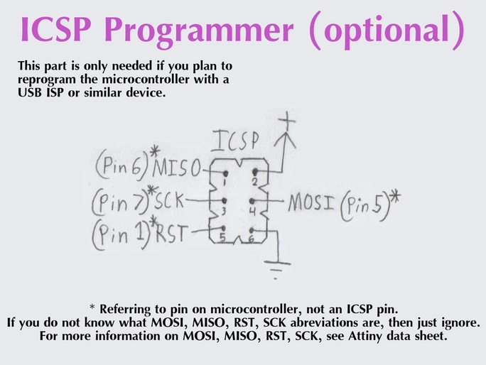
lastly and leastly is the ICSP programmer. This header allows you to reprogram the ATtiny if you have a USB ISP or similar device. I usually leave this part out because it is very unlikely that you would need to reprogram the ATtiny, and even if you do, the easiest way to program it is to take it out of the socket and wire it on a breadboard to your programmer. If you are using proto board, I would definitely recommend leaving it out because it is very difficult to solder.

